
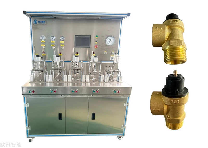
Combined Temperature & Pressure (T&P) Safety Valve Test Machine
Technical Proposal
| Item | Description |
|---|---|
| Products covered | Temperature & pressure safety valves. Product specification to be confirmed against customer samples and drawings; the current design allows for DN20/DN25 compatibility. |
| Test medium | Water — supports ambient water, circulating hot water and specified pressure conditions. |
| Test items | Pressure sealing, pressure opening, relief pressure, reseat pressure, temperature opening, temperature reseat, endurance, discharge/flow, external leakage. |
| Control | PLC + touchscreen + instrument / industrial PC data acquisition, supporting barcode binding, automatic testing, curve recording and report output. |
| Design basis | With reference to ANSI Z21.22 / CSA 4.4, GB 20910 and the customer’s product test specification. |
Objective: This proposal covers the construction of a combined T&P safety valve test machine that automates the inspection of pressure performance, temperature actuation performance, sealing performance, endurance and discharge data, improving test consistency, data traceability and the efficiency of production and development validation.
1. Overview
The combined T&P safety valve test machine simulates the pressure, temperature and discharge conditions a safety valve sees in a hot water supply system. Through pressurised water supply, temperature cycle control, fixture sealing, flow measurement, outlet state detection and automatic pressure relief control, the equipment completes the key performance tests of the safety valve and records the whole process automatically.
The machine has a modular design and consists mainly of a water circulation system, a pressure control system, a temperature control system, a test fixture system, a flow and state detection system, an electrical control system and a data acquisition and software system. The test sequence is managed through recipe parameters, accommodating products of different models, set pressures and set temperatures.
2. Design Basis and Scope
-
With reference to the requirements of ANSI Z21.22 / CSA 4.4 for the pressure element, temperature element, endurance and leakage performance of relief valves for hot water systems.
-
With reference to GB 20910 and the product drawings, inspection specifications and factory test requirements finally confirmed by the customer.
-
Supports in-line production testing, development validation, sampling retest and equipment acceptance testing.
-
This proposal is based primarily on water-circuit testing. If the customer requires full steam discharge capacity certification testing, a steam capacity test module can be configured separately, or a third-party type test facility can be used.
3. Main Technical Parameters
| No. | Item | Specification |
|---|---|---|
| 1 | Power supply | Three-phase five-wire AC 380 V, with reliable earthing and residual current protection |
| 2 | Installed power | Approximately 40 kW, to be confirmed against final heating power, pump set and number of stations |
| 3 | External air supply | 0.6 MPa, for pneumatic actuators used in clamping, sealing and valve actuation |
| 4 | External water supply | >0.1 MPa; filtration, make-up water and low-level protection recommended |
| 5 | Test medium | Ambient water / circulating hot water, 20–99 °C |
| 6 | Test pressure | Designed for a maximum of 15 bar; actual range confirmed against pump, pipework, fixture and product under test |
| 7 | Pressure measurement | 0–1.6 MPa, accuracy 0.1%, or configured to customer requirement |
| 8 | Temperature range | Ambient to 100 °C, with temperature control accuracy targeted at better than ±0.2 °C |
| 9 | Flow measurement | 0–176 L/h for micro-flow detection; 0–3 m³/h for discharge measurement |
| 10 | Sampling period | 0.1 s; records pressure, temperature, flow, level/outlet signal and station status |
| 11 | Construction | Aluminium profile / stainless steel frame; 304 stainless steel tank and wetted parts |
| 12 | Station configuration | Pressure test station, temperature opening station, temperature closing station and endurance station can be configured as required |
4. System Composition and Working Principle
| Module | Function |
|---|---|
| Pressure water supply | A variable-frequency booster pump, pressure vessel, pressure regulating valve and pressure sensor form a closed-loop pressure control, supporting pressure rise, holding, decay and automatic relief. |
| Temperature control | Comprises a water tank, temperature measuring vessel, heater, circulation pump, heat dissipation/cooling circuit and PT100 temperature sensors, providing preheating, heating, holding and cooling. |
| Test fixture | Fixtures customised to the safety valve port, using a threaded connection and sealing structure to ensure accurate location, reliable sealing and convenient changeover. |
| Flow detection | A small flow meter is used for seal leakage and opening instant judgement; a large flow meter is used for discharge or capacity data acquisition. |
| Outlet / level detection | Temperature opening and closing tests detect valve actuation state through a transparent tube, level sensor or outlet signal. |
| Electrical control | The PLC handles sequence actions, interlocks, automatic cycling and alarm handling; the touchscreen is used for recipe setting, status display and manual commissioning. |
| Data acquisition | Collects pressure, temperature, flow, station status, alarms and test results, forming serial-number-level traceability records and test reports. |
5. Test Items and Procedures
The test programme runs automatically. Each recipe contains product model, set pressure, set temperature, pressure rise rate, pressure decay rate, heating rate, cooling rate, flow threshold, hold time, cycle count and judgement limits.
5.1 Preparations Before Testing
| Step | Operation | Judgement / output |
|---|---|---|
| 1 | Confirm that power, air, water, drain, emergency stop and guard door are in order. | No alarm on the HMI; safety interlocks effective. |
| 2 | Scan or enter the product serial number and select the corresponding recipe. | Serial number bound to the recipe; start is blocked if no scan or if the recipe does not match. |
| 3 | Check the status of the pressure, temperature, flow and level/outlet sensors. | Sensor zero point, range and communication normal. |
| 4 | Install the sample; confirm port, thermal probe orientation, sealing face and fixture position. | Fixture in-position signal normal; no mechanical interference. |
| 5 | Fill at low pressure, vent air and check pipework and fixture for leakage. | Pressure and flow stable; no abnormal leakage. |
5.2 Pressure Sealing Test
| Step | Operation | Control conditions | Judgement / record |
|---|---|---|---|
| 1 | Close the relief valve, open the inlet valve, fill at low pressure and expel all air. | Low-pressure circulation for 10–30 s. | Pressure rise begins once venting is complete. |
| 2 | Raise pressure to the sealing test pressure. | Recommended value 0.95 × set opening pressure; rise rate adjustable. | Record P1 and the hold start time. |
| 3 | Hold at the sealing pressure and monitor outlet flow / dripping signal. | Hold for 30–60 s or as specified by the customer. | Pass if there is no continuous flow and no dripping; record maximum flow and pressure drop. |
| 4 | On failure, relieve pressure automatically and alarm. | Fixture may be opened once pressure has fallen to a safe level. | Record leakage, pressure drop or fixture fault code. |
5.3 Opening and Reseat Pressure Test
| Step | Operation | Control conditions | Judgement / record |
|---|---|---|---|
| 1 | After the sealing test passes, keep the sample mounted and confirm the test water temperature. | Ambient point or a temperature point specified by the customer. | Record T1 and initial P1. |
| 2 | Raise pressure from a safe level below the set pressure. | Start pressure recommended ≤0.8 × set pressure; rise rate per recipe. | Record the pressure rise curve. |
| 3 | When stable flow appears at the outlet or the opening threshold is reached, record the opening pressure. | Opening threshold can use the micro flow meter or outlet signal; debounce time adjustable. | Record P_open, T1, F2 and actuation time. |
| 4 | Continue adjusting pressure so the valve discharges at the specified flow. | Flow conditions per product specification or customer acceptance requirement. | Record P_relief, F1/F2; check the relief pressure limit. |
| 5 | Reduce pressure slowly, monitoring flow decay and the valve closing point. | Decay rate per recipe; signal below threshold held for the debounce time. | Record P_reseat; check the reseat pressure limit. |
| 6 | Repeat the same test point three times. | Each cycle returns to the start pressure and confirms no residual flow. | Output three readings, average, range and final judgement. |
5.4 Temperature Opening and Reseat Test
| Step | Operation | Control conditions | Judgement / record |
|---|---|---|---|
| 1 | Mount the sample in the temperature test fixture, ensuring the thermal probe is in the effective flow path of the circulating hot water. | Temperature probe as close as possible to the thermal bulb measuring position. | Record mounting state and station number. |
| 2 | Preheat the tank, fill the measuring vessel and establish circulation. | Production testing may preheat to approximately 85 °C, then heat through the vessel/pipe heating. | Record initial water temperature. |
| 3 | Establish the test pressure and circulation flow. | Pressure set per recipe; 1 bar may be used as a reference for in-line testing. | Heating begins once P1 is stable. |
| 4 | Heat at the set rate and monitor the outlet signal. | Heating rate adjustable; standard reference 2–3 °C/min. | Record T_open when the first stable outlet/level signal triggers. |
| 5 | Enter the cooling phase once opening has occurred. | Maximum temperature must not exceed equipment and product safety limits. | Judged as “does not open” if the upper limit is reached without opening. |
| 6 | Cool at the set rate and monitor the closing point. | Cooling rate adjustable; standard reference ≤3 °C/min. | Record T_reseat once the outlet signal has disappeared and held. |
| 7 | Repeat three times or as required by the customer. | A complete curve is recorded for each cycle. | Output opening temperature, reseat temperature, average and judgement. |
5.5 Temperature Closing / Sealing Verification
| Step | Operation | Control conditions | Judgement / record |
|---|---|---|---|
| 1 | After temperature opening, move the sample to the closing verification station or keep it in the cooling phase of the same station. | Target temperature may be set to approximately 85 °C or a closing verification temperature specified by the customer. | Record serial number and station number. |
| 2 | Clamp the sample and establish circulation so hot water flows over the thermal bulb. | P1 and T1 stable; outlet detection signal normal. | Record stable conditions. |
| 3 | Observe whether the outlet continues to discharge. | Observe for 30–60 s or as specified. | Pass if there is no continuous outlet signal. |
| 4 | On abnormality, check fixture sealing, sensor false signals and whether temperature is out of limit. | Judge the product non-conforming once equipment causes are excluded. | Record the fault code and retest result. |
5.6 Endurance Test
| Step | Operation | Control conditions | Judgement / record |
|---|---|---|---|
| 1 | Complete a baseline pressure or temperature performance test before endurance. | Record baseline open/close points and curves. | Form the pre-endurance data set. |
| 2 | Pressure endurance: cycle opening, discharge and reseat at the set pressure. | Number of cycles as required by the customer; 100 cycles as a standard reference. | Record cycle count, peak pressure and number of anomalies. |
| 3 | Temperature endurance: cycle opening and closing at the set temperature. | Cycle in hot water above the opening temperature; number of cycles per recipe. | Record opening/closing signals and temperature curves. |
| 4 | Retest pressure, temperature and sealing performance after endurance. | Retest method as in 5.2–5.4. | Pass if retest results meet the limits. |
| 5 | After completion, inspect the body, sealing face, marking and actuation state. | No sticking, no external leakage, marking legible. | Record visual and functional inspection results. |
5.7 Discharge / Flow Test
| Step | Operation | Control conditions | Judgement / record |
|---|---|---|---|
| 1 | Select the product’s rated discharge capacity or a flow condition specified by the customer. | Choose the small or large flow meter according to flow magnitude. | Recipe locks the range and sampling duration. |
| 2 | Open the valve under the specified pressure or temperature condition and allow it to stabilise. | Pressure, temperature and flow enter the stable band. | Record the start and end of the stable period. |
| 3 | Acquire instantaneous flow continuously and calculate average discharge. | Sampling of ≥60 s recommended, or as specified by the customer. | Output average flow, maximum/minimum flow and total discharge. |
| 4 | Compare against the customer’s limit or the product rating. | Water discharge judged in L/h or m³/h. | Save the calculated results and curves. |
6. Acceptance Criteria and Data Output
| Test item | Judgement principle | Data output |
|---|---|---|
| Pressure sealing | No continuous flow and no dripping at a sealing pressure below the set opening pressure; pressure drop meets the customer’s limit. | Sealing pressure, hold time, maximum flow, pressure drop, judgement |
| Opening pressure | Judged against the customer’s product specification; a reference range of 90%–105% of set pressure may be used. | Three opening pressures, average, range, test temperature |
| Relief pressure | Relief pressure at the specified flow meets the product limit; reference requirement: not more than 110% of opening pressure. | Relief pressure, flow, stabilisation time |
| Reseat pressure | The valve closing point meets the product limit; reference requirement: not less than 80% of relief pressure. | Reseat pressure, closing threshold, closing time |
| Temperature opening | Judged against the product’s specified temperature; reference requirement: within ±5.5 °C of set temperature and not above 99 °C. | Opening temperature, pressure, heating rate, outlet signal |
| Temperature reseat | Reseat temperature meets the customer’s limit; reference requirement: a deviation limit of not less than 14 °C below the set opening temperature. | Reseat temperature, cooling rate, outlet signal |
| Endurance | After cycling, retested pressure, temperature and sealing performance still meet the limits. | Cycle count, anomaly count, pre/post endurance data, deviation |
| Discharge | Average flow or total discharge meets the customer’s requirement. | Average flow, total discharge, sampling duration, pressure and temperature curves |
7. Software Functions
| Function | Description |
|---|---|
| Recipe management | Maintains product model, set pressure, set temperature, rates, thresholds, hold time, cycle count and judgement limits. |
| Barcode traceability | Scanning starts the test and automatically binds serial number, recipe, station, time, operator and test results. |
| Automatic testing | Controls valves, pumps, heating, fixtures, drain and pressure relief automatically according to the test steps. |
| Real-time monitoring | Displays pressure, temperature, flow, level/outlet signal, fixture status, alarm status and current step. |
| Curve recording | Records pressure, temperature, flow and digital states at 0.1 s sampling, with curve viewing. |
| Report output | Generates individual reports and batch statistics automatically, outputting pass rate, average, range, fault codes and similar data. |
| Access control | Recipe modification, retesting, data deletion and manual commissioning require access permission. |
8. Safety Protection
-
Over-pressure protection: stops pressure increase and relieves automatically when pressure exceeds the set upper limit.
-
Over-temperature protection: stops heating and starts cooling/drain protection when water temperature exceeds the set upper limit.
-
Low water level / no water protection: prevents dry heating of the heater and dry running of the pump.
-
Fixture interlock: testing is blocked when the fixture is not in position or the guard door is not closed.
-
Emergency stop protection: on emergency stop, closes key actuators and enters a safe pressure relief sequence.
-
Sensor fault protection: stops the machine and alarms, recording a fault code, when pressure, temperature, flow or level signals are abnormal.
9. Main Equipment List
| No. | Item | Specification / description | Qty |
|---|---|---|---|
| 1 | PLC controller | SMART 200 series or equivalent | 1 set |
| 2 | Touchscreen | 7–10 inch, configured to final interface requirements | 1 set |
| 3 | Industrial PC / data system | For data acquisition, reports and curve recording | 1 set |
| 4 | Pressure sensor | 0–1.6 MPa, 0.1%, or to customer requirement | Per station |
| 5 | Temperature sensor | PT100, measuring points configured per circuit | Per station |
| 6 | Small flow meter | 0–176 L/h, for sealing and opening judgement | Per station |
| 7 | Large flow meter | 0–3 m³/h, for discharge testing | 1 set |
| 8 | Booster pump / circulation pump | Variable-frequency control, selected to pressure and flow demand | As required |
| 9 | Heating system | Tank heating, vessel/pipe heating | Per design |
| 10 | Test fixture | DN20/DN25 or customised to customer sample port | Per station |
| 11 | Tank and pipework | 304 stainless steel wetted parts | 1 set |
| 12 | Electrical components | Circuit breakers, switch-mode power supplies, relays, pushbuttons, indicator lights, etc. | 1 set |
10. Delivery and Acceptance
| Acceptance item | Content | Pass requirement |
|---|---|---|
| Appearance and structure | Machine outline, installation quality, markings, pipework layout, maintenance access. | Structure complete, markings legible, operation and maintenance convenient. |
| Pressure control | Pressure rise, holding, decay and relief actions. | Pressure control stable; no abnormal overshoot or leakage. |
| Temperature control | Preheating, heating, holding and cooling actions. | Temperature curve stable; meets the set range and rate requirements. |
| Test sequence | Pressure sealing, pressure open/close, temperature open/close, endurance and discharge sequences. | Automatic sequence complete; steps and judgement logic conform to the agreed proposal. |
| Data traceability | Barcode scanning, curves, reports, anomaly records. | One-to-one correspondence between serial number and test data; reports queryable and exportable. |
| Safety interlocks | Emergency stop, over-pressure, over-temperature, fixture not in position, no water and similar protections. | Alarms and stop actions effective; relief and cooling sequences reliable. |
11. Notes on the Proposal
-
The pressure, temperature and flow ranges in this proposal are compiled from current requirements and standard reference values; final parameters are subject to confirmation against customer samples, drawings and acceptance criteria.
-
To cover the full ANSI/CSA steam discharge capacity test, dedicated modules for a steam boiler, condensate weighing and 121 °C exposure must be added, or the test carried out as a third-party type test item.
-
Before manufacture, the sample port, fixture type, number of stations, cycle time requirements, report format and communication interface must be confirmed.
12. Reference Illustrations
Software interface