
Air Valve Flow Test Bench
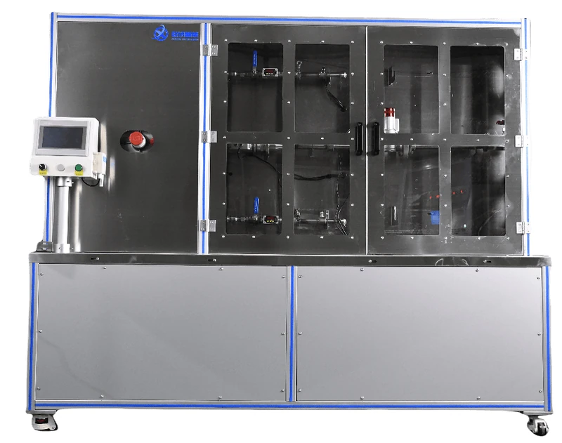
Air Valve Flow Test Bench
For gas-service valves and emergency shut-off valve samples, to measure rated flow under agreed inlet-pressure and differential-pressure conditions to compare valve flow capacity. Circuits and fixtures are selected for the sample and required tests.
Product Overview
Application and test scope
Air Valve Flow Test Bench is intended for gas-service valves and emergency shut-off valve samples. It is used to measure rated flow under agreed inlet-pressure and differential-pressure conditions to compare valve flow capacity. The test arrangement is selected around the sample construction, service conditions and required evaluation method.
Tests and configuration
- Matching flowmeters and fixtures to valve sizes
- Establishment and observation of inlet pressure and differential pressure
- Rated-flow readings linked to sample identifiers
Typical test workflow
Select the flowmeter, fixture and adapters for the valve size, confirm sealing and valve state, then read flow after the agreed pressure and differential pressure have stabilised. The medium and conditions follow the test plan.
Selection information
For a suitable proposal, provide valve size, connections, test medium, rated-flow range, inlet pressure, differential pressure and readout method. Product drawings or a sample help define connections, locating tooling and test circuits.
Measurement ranges, accuracy, automation, data interfaces and acceptance criteria are defined by the selected configuration and agreed technical proposal.
Existing equipment information
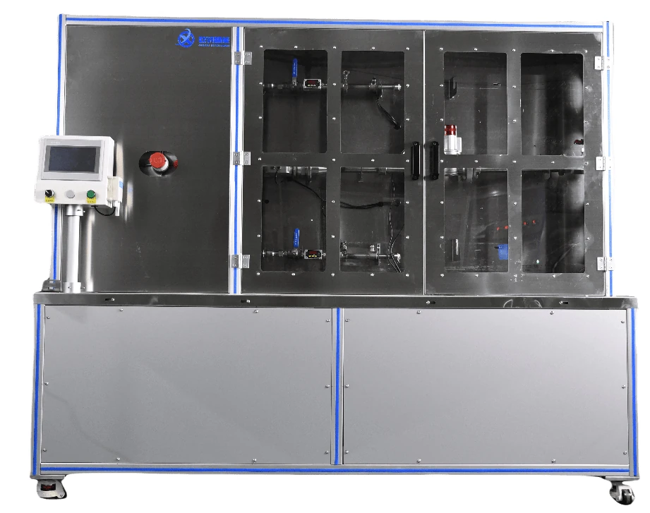
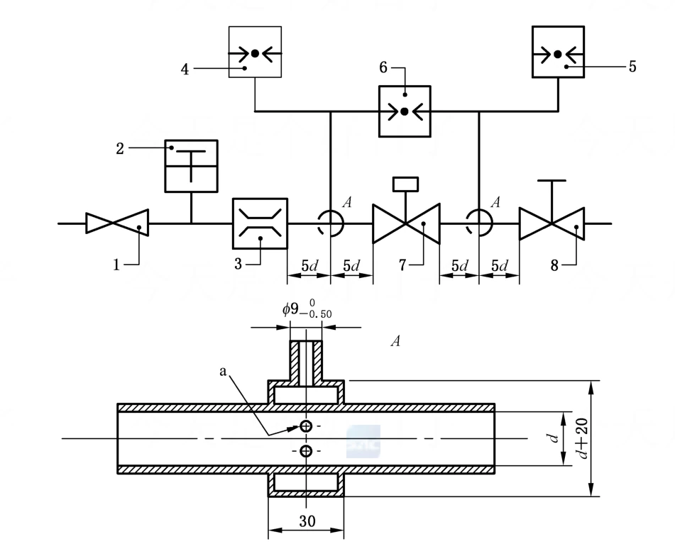
Rated flow testing of gas valves is performed on equipment developed in accordance with the industry standard GB 44016-2024 for solenoid-operated emergency gas shut-off valves.
To accommodate six valve sizes — DN15, DN20, DN25, DN32, DN40 and DN50 — while maintaining measurement accuracy, the test fixture is designed in three groups: DN15–DN20, DN20–DN32 and DN40–DN50. Within each group the chuck connector can be exchanged to match different interface types and valve sizes.
Test procedure
1. Fit the flow meter and fixture — select the flow meter and the corresponding fixture according to the valve to be tested.
2. Clamp and seal — fit the appropriate inlet and outlet connectors, tighten them by hand and open the ball valve under test.
3. Test — switch on the power supply and the inlet air supply ball valve, manually adjust the filter pressure-reducing valve to an outlet pressure of 3 bar, then adjust the secondary pressure regulator until the inlet pressure gauge reads 2.5 kPa. Manually adjust the exhaust shut-off valve until the differential pressure gauge reads approximately 100 Pa. The flow indicated by the flow meter under these conditions is the rated flow of the ball valve.
Interested in this equipment?
Tell us your testing needs — we will tailor a solution for you
Email Inquiry