
Upright Metallurgical Microscope
Upright Metallurgical Microscope
For metal, ceramic and electronic samples suitable for optical observation, to select objectives, illumination and observation modes for microstructure, surface-defect and morphology inspection. Circuits and fixtures are selected for the sample and required tests.
Product Overview
Application and test scope
Upright Metallurgical Microscope is intended for metal, ceramic and electronic samples suitable for optical observation. It is used to select objectives, illumination and observation modes for microstructure, surface-defect and morphology inspection. The test arrangement is selected around the sample construction, service conditions and required evaluation method.
Tests and configuration
- Observation of microstructure, cracks and surface defects
- Reflected or transmitted illumination selected for sample transparency
- Image capture and dimensional measurement where configured
Typical test workflow
After the required sectioning, grinding, polishing or surface preparation, select objectives and illumination and focus on the region of interest. Dimensional measurement requires the corresponding calibration and software configuration.
Selection information
For a suitable proposal, provide sample material, dimensions and thickness, feature of interest, illumination, objectives, working distance and image-capture requirements. Product drawings or a sample help define connections, locating tooling and test circuits.
Measurement ranges, accuracy, automation, data interfaces and acceptance criteria are defined by the selected configuration and agreed technical proposal.
Existing equipment information
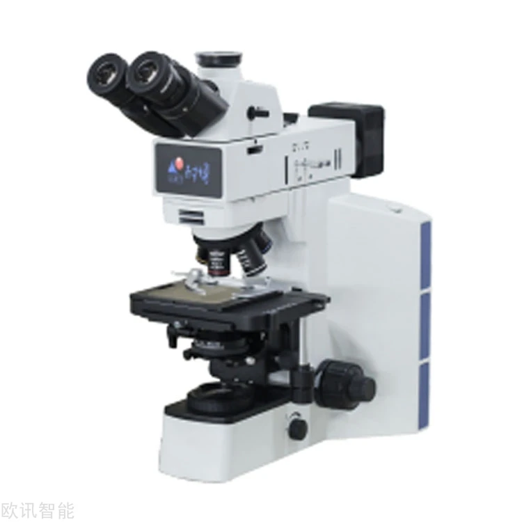
1. Structure and Operating Principle
1.1 Optical system
Objective: high-magnification objectives (e.g. 5×–100×) enlarge specimen detail; achromatic and plan achromat objectives are commonly used to minimise aberration.
Eyepiece: 10× or 15× eyepieces provide further magnification, and some models are fitted with a digital camera interface for image capture.
Illumination: transmitted light (for transparent or semi-transparent specimens) and reflected light (for opaque specimens such as metals and ceramics) are both available; LED sources have become the mainstream choice thanks to their long service life and high stability.
1.2 Mechanical structure
Stage: a high-precision mechanical X-Y stage allows accurate specimen positioning, and some models support motorised control.
Focusing mechanism: coarse and fine adjustment knobs ensure precise focusing for specimens of different thicknesses (e.g. PCB panels, metallographic sections).
2. Core Application Areas
2.1 Materials science
Metallographic analysis: observation of the microstructure of metals and alloys, such as grain size and phase distribution.
Ceramics and composites inspection: analysis of porosity, cracking and interface bonding condition.
2.2 Electronics manufacturing
PCB inspection: checking solder joint quality and circuit defects such as short circuits and dry joints.
Semiconductor packaging: inspecting die surface scratches and lithography alignment accuracy.
2.3 Precision machining and quality control
Tool wear analysis: assessing microscopic wear of the cutting edge.
Surface roughness measurement: 3D topography analysis using dedicated software.
3. Technical Features
3.1 High resolution and stability
An infinity-corrected optical system reduces aberration for sharper images.
An anti-vibration base copes with the vibration present in factory environments.
3.2 Versatile expandability
Optional dark field, polarised light and DIC (differential interference contrast) observation modes enhance image contrast.
Works with industrial cameras and image analysis software for measurement, counting and particle analysis.
3.3 Durability
The predominantly metal housing resists corrosion and wear, making the instrument suitable for long-term heavy-duty use.
4. Selection and Maintenance
4.1 Key selection parameters
Magnification: select the objective combination according to the inspection task (e.g. 20×–200×).
Working distance: long working distance objectives suit raised or uneven specimens.
Illumination mode: reflected light for metals and highly reflective materials; transmitted light for films and transparent bodies.
4.2 Maintenance
Clean the optical components regularly using professional lens tissue and cleaning fluid.
Avoid high temperature and high humidity to prevent fungus forming on optical elements.
Calibrate the stage travel accuracy periodically to keep measurement results reliable.
Interested in this equipment?
Tell us your testing needs — we will tailor a solution for you
Email Inquiry