
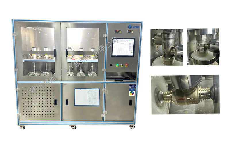
Ouxun Intelligence · Technical note
“Can a PN16 valve be tested at 2.4 MPa?” The answer depends on where the number comes from and which test is being performed. A sound test plan separates pressure-resistance testing from seat tightness, states the medium and acceptance criteria, and records the actual conditions.
The notes below refer to documents such as GB/T 13927 and ISO 5208. Valve product standards and the signed technical agreement for a project take priority.

1. PN is not MPa: the 2.4 MPa value must be calculated
PN is a nominal pressure designation. The “16” in PN16 is not 16 MPa and is not automatically the valve’s allowable working pressure. Material, temperature and the applicable rating table all matter.
CWP means cold working pressure. When a project uses CWP as the calculation basis, first identify it from the applicable standard, manufacturer data or an approved technical document, then apply the specified multiplier.
For example, if the approved documentation gives CWP = 1.6 MPa and the liquid shell test is specified as 1.5 times CWP, the target is 2.4 MPa. The value comes from 1.6 × 1.5, not from the PN marking. Class 150 and Class 300 ratings also require the material group and temperature rating table; their numbers are not a direct MPa conversion.
Write down the valve model, size, material and rating mark; the source and temperature for the rating; the test name and calculation basis; the target pressure; and whether the pressure is gauge or absolute.
2. Shell and seat tests check different locations
“Pressure test passed” is not enough for a report. The test location, valve state, method and acceptance rule differ by test item.
| Test item | What it checks | What the procedure must state |
|---|---|---|
| Shell test | Integrity and external leakage of the pressure boundary and connections | Valve position, medium, pressure, hold time, inspection points and criteria |
| Seat tightness test | Leakage through the closed sealing pair at the specified differential pressure and direction | Closing method, pressure direction, differential pressure, detection method and limit |
| Back-seat test | Back-seat performance where this construction applies | Applicability, operating state and procedure |
3. Water and gas tightness are different test conditions
Replacing a gas test with a water test, or changing only the pressure number, does not create an equivalent test. The medium affects safety, compressibility, detection method and the meaning of the result. Follow the applicable standard and agreement for the product.
Confirm medium compatibility with the body and seals, cleanliness, medium temperature and ambient conditions. For stainless-steel parts, check any water-quality, chloride-content and post-test drying requirements. Vent trapped air from a liquid test and allow a gas test to reach the specified equilibrium. Match the pressure limit, depressurization route, guarding and interlocks to the assessed risk. Equipment pressure capability alone does not authorize a test condition.
4. A fixture must hold the part without changing the result
Fixtures influence alignment, sealing force and deformation. Record fixture identification, clamping setting, closing method and any required torque. Gas tests require additional risk controls because stored energy is higher.
Excessive clamping force can deform thin-walled bodies, small valves and sensitive sealing structures. Insufficient force or unsuitable fixture seals can produce fixture leakage that is wrongly attributed to the valve. Neither a claim of “no additional force” nor a blanket judgment that one fixture type is inaccurate is sufficient: inspect the load path, suitability, repeatability of the clamping setting and the fixture’s own sealing verification.
Ask where the clamping force enters the test article; how it is set, limited and reproduced between operators; how fixture leakage is distinguished from valve leakage; which locators, seals and recipes change with size; and whether unclamping is interlocked until depressurization is complete. Where practical, refit the same valve three to five times and compare results under identical medium, pressure, stabilization and decision conditions.

5. “Zero leakage” must specify the conditions
A zero-leakage statement is meaningful only with the medium, pressure or differential pressure, temperature, stabilization time, observation method, duration and allowed value. Gas bubble count, quantitative flow and pressure-drop methods have different limits and cannot be compared without their conditions.
GB/T 13927 and ISO 5208 specify leakage classifications; reference the applicable class together with the medium, differential pressure, duration, method and units. “Zero leakage” normally means no leakage detected by the specified method under the specified conditions, rather than absolute zero under every operating condition.
For bubble testing, use the specified apparatus and counting procedure; bubble count cannot be converted directly to volumetric flow without its conditions. Quantitative flow measurement needs units and measurement conditions, including the reference state for gas. Pressure-drop results depend on test volume, temperature fluctuation, stabilization and background system leakage; validate these influences before equating a pressure change with seat leakage. Helium mass-spectrometer testing also requires its own method basis and acceptance limit; changing instruments does not establish equivalence to a bubble test.
Put the purchasing requirements into the acceptance record
| Confirmation item | Record |
|---|---|
| Test article identity | Model, serial number, DN, PN or Class, main material and sealing construction |
| Document basis | Applicable standard and edition, product standard and technical agreement number |
| Pressure basis | Rating source, target test pressure or differential pressure, actual pressure |
| Test and direction | Shell, seat or other applicable item; pressure direction and valve state |
| Test conditions | Medium, temperature, stabilization time and effective hold time |
| Fixture and operation | Fixture ID, clamping setting, closing method and required torque record |
| Detection and decision | Method, instrument range, unit, allowed value and actual result |
| Traceability | Instrument ID and calibration validity, date, operator and original record |
For automated equipment, agree how pressure–time curves, alarms, recipes and results are stored. A curve can reconstruct the process but cannot replace the leakage observation or quantitative measurement required by the test item.
Frequently asked questions
Can a PN16 valve be set directly to 2.4 MPa?
Not from the PN mark alone. Confirm the rating basis and the specified test item first. The 2.4 MPa example requires CWP = 1.6 MPa and a 1.5× liquid shell-test rule; the project standard and agreement govern the real value.
Seat tightness uses a different pressure, often 1.1 times CWP where the adopted requirements specify it. Do not copy the shell-test pressure into a seat-test recipe.
Can we perform only a water test and skip the gas test?
Only when the applicable standard, valve requirement and technical agreement allow it. A water test does not automatically replace a gas tightness test.
Is a higher pressure or longer hold time safer?
No. Exceeding the approved procedure can damage the test article and changes the risk. Define the purpose, method and criteria before execution.
Does a pressure curve prove seat tightness?
No. A curve shows how pressure changed. Tightness still requires the specified detection method, allowed value and test conditions.
About Ouxun Intelligence
Ouxun Intelligent Technology (Taizhou) Co., Ltd. provides custom and standard test equipment for valve, HVAC, sanitary, pipe, hose and related products. We develop proposals around the product, test method, fixture, medium, pressure or flow range, stations, cycle time and data records.
This article is a general technical reference. It does not replace the applicable standard, product specification, approved procedure or signed technical agreement. The pictured equipment is illustrative and does not by itself prove pressure capability, accuracy or certification. How hold time and judgment timing are set is covered in hold time and leakage criteria; how hydraulic and pneumatic acceptance wording differ on the same valve is broken down in API 598 vs GB/T 13927; current editions and scopes are summarized in the Valve Test Standards Index.
Related test equipment
Each test above maps to a bench. Pick by valve type and by the item you need to prove:
- Valve pressure test machine — shell at 1.5x and seat at 1.1x, with a report per valve
- Valve torque test machine — break-to-open and seating torque curves for actuator sizing
- Pipe and connection leak test bench — pressure-decay and helium methods, judged against a leak-rate limit
- Valve testing equipment range — browse all models by valve type and test item