
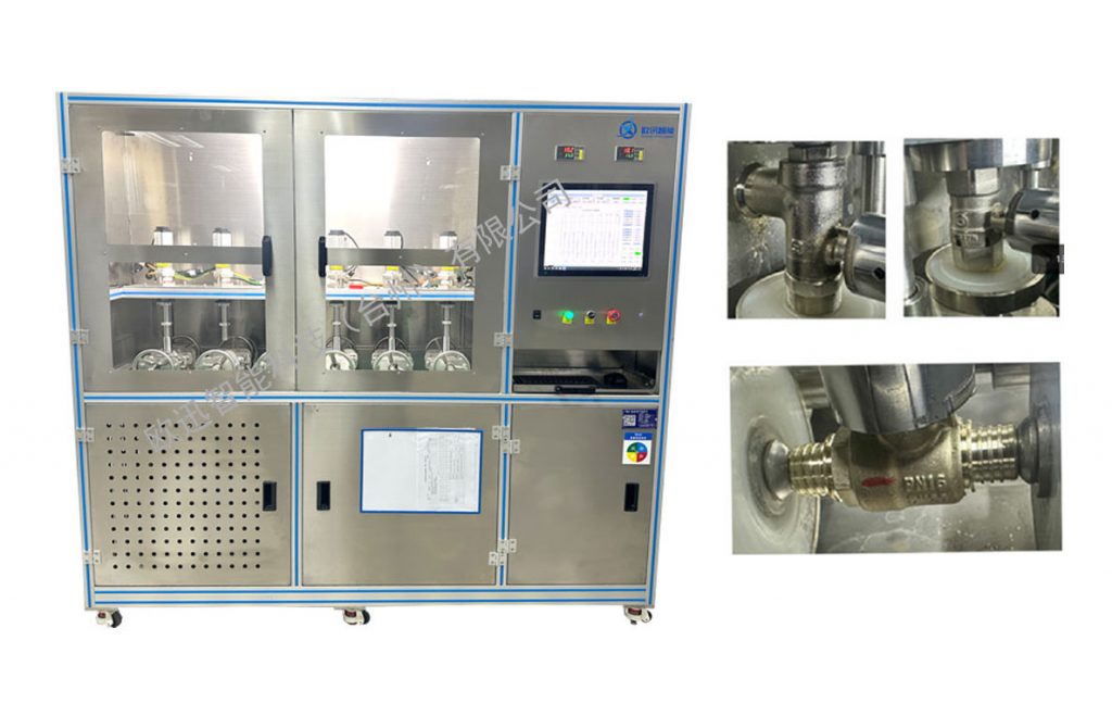
Start with the test type, not the specification sheet. The same bench configured for routine factory release and for a witnessed type test can differ in price by a factor of two. Run it the other way round – take a fast production bench to a third-party inspection – and you usually fail on data records and safety interlocks, not on pressure capability.
Everything downstream, the pressure range, the size coverage, the fixtures and the acceptance rules, is derived from that one question. So the sequence is: fix the test type, derive the required capability, state pressure and size properly, settle the acceptance rule, then write the terms into the contract.
Step one: decide which of the three test types you are actually doing
What the industry calls “valve testing” is three quite different activities. Discuss them as one and you will buy the wrong machine.
| Test type | Purpose | Basis | Frequency | What the equipment must do |
|---|---|---|---|---|
| Factory release test | Prove this batch can ship | Product standard plus internal inspection spec | Every unit or sampled | Fast cycle, quick changeover, automatic verdict |
| Type test | Prove the design of this model is compliant | Full scope of the national or industry standard | New design, major change | Full parameter coverage, traceable data, formal report |
| Post-repair check | Prove the valve still works after repair | Original design parameters plus repair procedure | Every repair | Controllable pressure, adequate guarding, raw value records |
When the boundary between these is blurred, the typical failure looks like this: you buy a fast production bench, then a customer audit asks for the raw pressure curve and operator record from the shell strength test – and the machine can only print a single line saying “pass”. That is scored as insufficient evidence.
The opposite waste is just as common. Buying a full-range, full-parameter machine for a type test you run once every few years leaves capacity idle for the rest of the year and stretches the payback period badly.
The way to decide is simple enough: pull the last twelve months of test records, sort them into the three categories above, and count. The category that accounts for roughly eighty percent of the volume decides the machine. The other two decide how much headroom you need to leave.
For the boundaries between the three, see planning valve tests across factory, type and post-repair scopes. If shell strength and seat tightness are still being used interchangeably in your plant, start with the difference between hydrostatic and air-tightness benches.
If the product falls under China’s special-equipment catalogue and a type-test certificate is required, it is not simply “a few more items”: the item list, sample quantity and coverage range follow a statutory regulation — see TSG D7002-2023 valve type testing: items and coverage.
Step two: work backwards from the test type to the required capability
Once the type is fixed, the capability list follows. This is the table to tick through line by line during selection.
| Test item | Key parameters | Capability the equipment must have | Most common shortfall |
|---|---|---|---|
| Shell strength | 1.5 times nominal pressure, hold duration | Stable pressurisation, accurate hold, overpressure protection | Pressurisation rate uncontrolled, overshoot then sag out of tolerance |
| Seat tightness | 1.1 times nominal pressure, allowable leakage | Micro differential pressure measurement, long-term stability | Sensor range too wide, small leakage invisible |
| Air tightness | Test pressure, leak detection method | Whatever the chosen method needs (pressure decay, flow, bubble, tracer) | Only pressure decay available, inaccurate on large-volume parts |
| Flow characterisation | Differential pressure, temperature, Cv/Kv | Multiple operating points, temperature compensation, automatic venting | Differential pressure unstable, Kv values not comparable |
| Endurance and cycling | Cycle count, actuation time | Cycle counting, timeout alarm, automatic stop | No exception logging, failure location unidentified |
The column to watch is the last one. Range and accuracy on the datasheet are usually fine. What actually sends a project back for rework is pressurisation rate, sensor range matching and exception logging – the things that never appear on the front page of a brochure.
For the pressure clauses themselves, GB/T 13927-2022 is the reference most often cited in China; its test pressure values and hold-time bands are covered in this clause-by-clause walkthrough. How long to hold is treated separately in the size-banded reference table, so it is not repeated here.
Step three: state the pressure parameters properly, not as a single nominal figure
The most common enquiry reads “I need a bench that can go to PN16”. That sentence is missing at least three things.
First, PN and CWP are not the same. PN is a nominal pressure class – an identifier corresponding to the allowable pressure of a given material at 20°C. CWP is cold working pressure, the pressure the valve can actually hold given its body material. A valve marked PN16 with a cast iron body may have a CWP noticeably below PN16. Deriving test pressure from PN alone goes wrong the moment cast iron enters the picture.
Second, the multiplier depends on the test type. Shell strength is usually 1.5 times nominal, seat tightness 1.1 times – the common practice under GB/T 13927 and API 598. But customer specifications and third-party inspections frequently tighten this, for example requiring shell tests at 1.5 times with a hold of not less than 300 seconds. If the multiplier is not confirmed before quotation, you discover on site that the pump station cannot reach the required pressure, and you pay for a new pump.
Third, the pressurisation method decides whether the machine is usable in your plant. Pneumatic intensifiers are cheap and clean but limited by the air supply. Hydraulic intensifiers reach high pressure but bring medium handling, drainage and corrosion questions. Servo-electric pressurisation gives the best control at the highest cost. Which one you need depends on your pressure ceiling, your cycle time and whether the shop has an air supply at all.
The PN versus CWP distinction, and what to clarify before pushing a PN16 valve to 2.4 MPa, is set out in this note on PN, CWP and test pressure. Where custom pressure boundaries and guarding are involved, the boundary conditions for a custom bench goes into more detail.
Step four: size range, connection types and changeover time
Size range is easy to understand. What gets underestimated is changeover time.
A bench covering DN15 to DN300 that needs the flange unbolted, the seal changed and the part re-centred on every size change costs twenty minutes per changeover. Change ten sizes a day and you have lost more than three hours. On a high-mix, low-volume line, changeover routinely takes longer than the test itself.
So the question is not “what is the largest size it can take”. The three questions that matter are:
- 1. How many people and how many minutes does a changeover take? Ask for a measured figure, not an estimate.
- 2. Are the fixtures universal or dedicated? Universal fixtures change over quickly but clamp with limited force; dedicated fixtures seal reliably but you need one set per size.
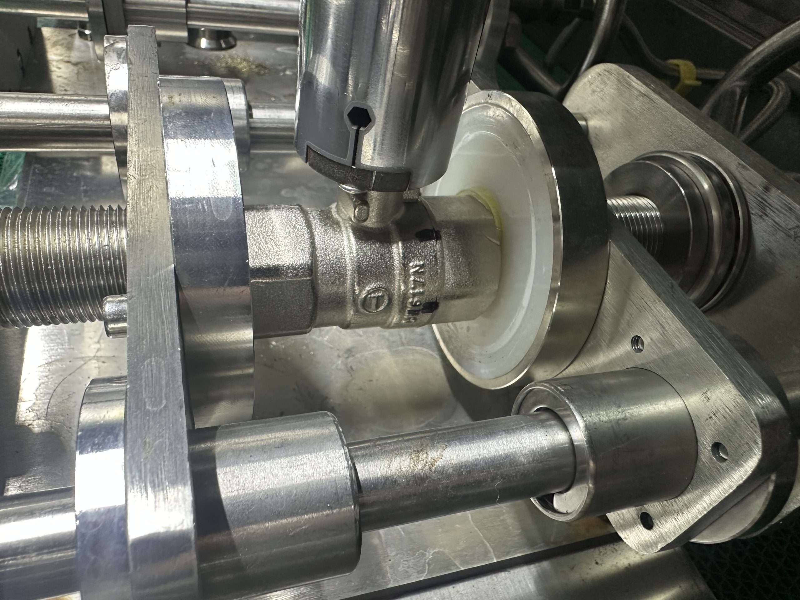
- 3. Which connection types are covered? Flanged, threaded, clamped and welded each clamp differently. Clamp connections in particular seal by radial compression, so the fixture has to hold the ferrule axially while sealing against it – a different mechanism from a flange bolted face to face.
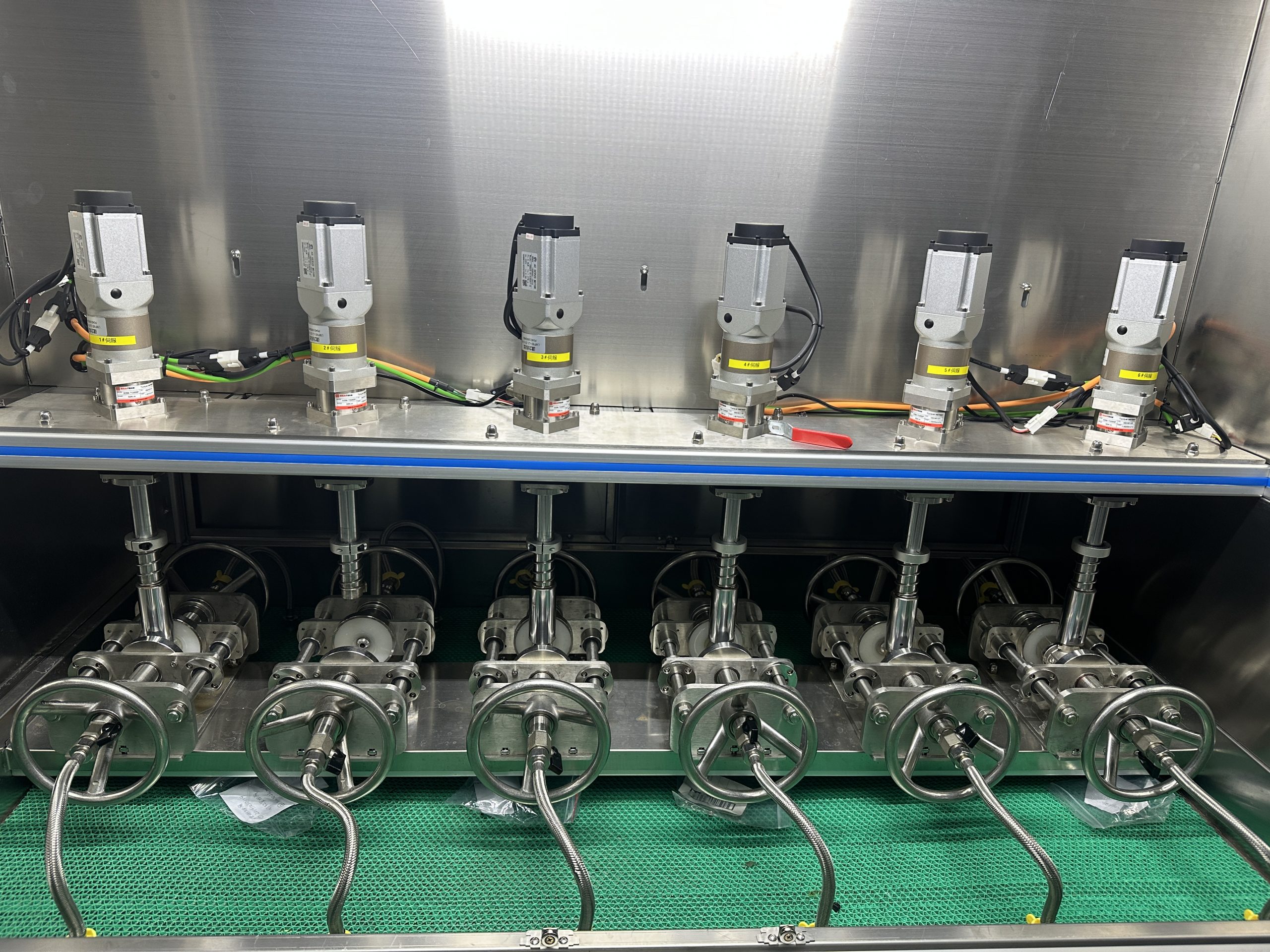
One more item that is routinely forgotten: traceability of the machine’s own instrumentation. Pressure gauges, transducers and flow meters all need calibration certificates, and those certificates must trace back to a higher-level standard. Confirming what certificates the supplier delivers, how long they are valid and how recalibration is handled is more useful than arguing over the last decimal place of sensor accuracy. The checking method is described in calibration, range and traceability chains for flow and differential pressure equipment.
Step five: if the acceptance rule is not settled, nothing else matters
This is the part most often deferred to the end, and the part that causes the most trouble. “Is it leaking” is not a technically meaningful question. It has to become “how much leakage counts as a pass”.
The five common leak detection methods differ substantially in where they apply:
| Method | Principle | Best for | Sensitivity | Limitation |
|---|---|---|---|---|
| Pressure decay | Hold pressure and watch it fall | Small to medium volume, rigid parts | Medium | Temperature-sensitive on large or elastomer-containing parts |
| Flow measurement | Measure the make-up flow directly | Quantification, continuous monitoring | Medium-high | Needs stable supply and a flow meter |
| Bubble immersion | Immerse or apply liquid, watch bubbles | Quick shop-floor judgement, large parts | Low | Subjective, produces no data |
| Tracer gas | Helium or similar with mass-spec detection | High-specification, micro-leakage | Very high | Expensive, needs gas supply |
| Vacuum | Evacuate and measure rise or use mass spec | Sealed cavities, special structures | High | Part must be evacuable |
Pick the wrong method and everything downstream is wasted effort. Run pressure decay on a large-volume part with a rubber diaphragm and the reading drifts with temperature, so the verdict changes from day to day – which is exactly the most common cause of unstable air-tightness results.
The acceptance criterion itself needs a source. Metal-seated and soft-seated valves are not in the same order of magnitude. ISO 5208 grades leakage from A to G; soft-seated valves are normally held to rate A (no visible leakage), while metal-seated valves are relaxed according to size and class. Apply one acceptance line to both designs and you will misjudge on one side and under-detect on the other.
The trade-offs between the five methods are compared in pressure decay, flow, tracer gas and vacuum compared. For the troubleshooting order when results keep flipping, see the five leak points checklist.
Flow characterisation: being able to compute Cv/Kv is not the same as computing it correctly
The trap in flow testing is not the hardware, it is comparability of data. The same valve, tested at a different differential pressure, a different temperature or with a different sampling approach, will show Kv values that differ by more than ten percent.
Four conditions have to hold for the numbers to be comparable: stable differential pressure (past five percent of setpoint, repeatability is gone), temperature compensation (water viscosity and density change with temperature), multiple operating points (at least three to five openings – a single full-flow reading says nothing about characteristic), and range matching (a sensor range an order of magnitude above the measured value turns the low-flow region into pure noise).
The definitions of Cv and Kv, and how test conditions affect the result, are explained in Cv and Kv: definitions, test conditions and the limits of the report. At selection stage you need the full chain from Cv/Kv definition to acceptance data and how to check range, measurement chain and acceptance method.
Endurance and cycling tests: the cycling logic has to be traceable
An endurance test looks simple – cycle until failure or until the specified count. What separates a good bench from an adequate one is whether it can answer: at which cycle did it fail, during which part of the stroke, and what were the pressure and flow at that moment.
Four things are non-negotiable:
- 1. Accurate cycle counting that survives a power interruption.
- 2. Actuation timeout alarm, so a sticking valve stops the test instead of being forced through.
- 3. Synchronised pressure and flow logging keyed to the cycle number.
- 4. Savable test recipes, so switching valve types does not mean re-entering parameters.
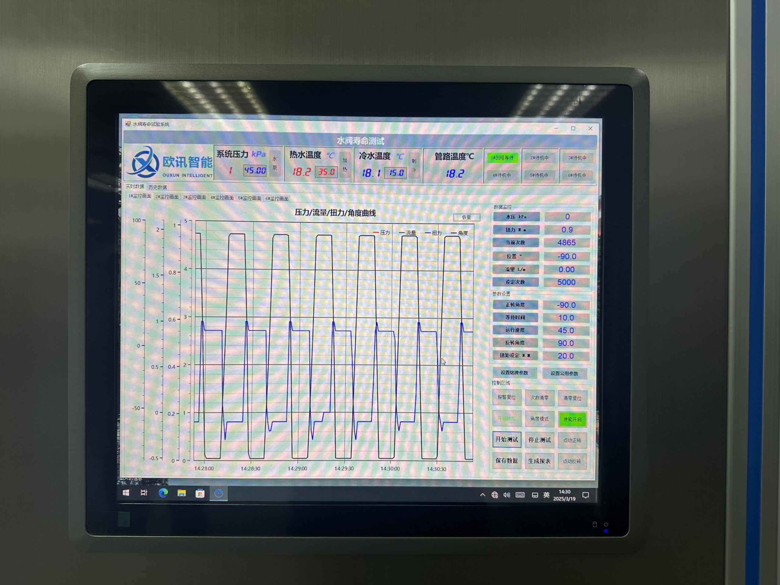
For thermostatic, mixing and pressure reducing valves, endurance also has to include performance decay. Passing does not mean “it still moves”; it means “after N cycles, the key performance is still inside the specified band”.
The field FAQ on valve endurance testing covers fixturing, cycling and interpreting results. For pressure cycling, see waveform and acceptance for pressure fatigue testing; for tests with thermal cycling, how to define conditions for a thermal shock rig.
Valve-type specifics: four families with different requirements
The framework above is general. Each valve family has its own weak point.
Safety valves: set pressure, reseat pressure and tightness are three separate things
A safety valve test covers three items, not one: set pressure (when it lifts), reseat pressure (when it closes again), and seat tightness (whether it leaks when closed). Plants routinely conflate them and issue a report on lift pressure alone, which does not survive a third-party audit.
The bench has to record the complete lift and reseat curve, not just a peak value. Method and common errors are covered in what a safety valve test bench actually measures; for automated configurations see the scope and limits of an automatic safety valve test machine, and for defining the project scope, the applicable boundaries of set, reseat and tightness.
Pressure reducing valves: stability at the outlet while the inlet moves
The point of a pressure reducing valve is not that it reduces pressure. It is whether the outlet stays stable when the inlet fluctuates, and how far the outlet drifts as flow changes. Those two determine the accuracy and response of the regulating loop, and an ordinary pressure bench cannot do it.
GB/T 12245 is the main basis for pressure reducing valve performance testing; clause checking before implementation is in this reading of GB/T 12245-2025, and how equipment functions map to those clauses is in selecting test equipment for pressure reducing valves.
Thermostatic and mixing valves: temperature response is a different logic
Thermostatic mixing valves, thermostatic radiator valves and thermostatic balancing valves are judged on temperature response speed and flow distribution, not on pressure tightness. The bench has to hold the hot and cold inlet conditions stable and log the outlet temperature response curve.
Inlet conditions and outlet response for thermostatic mixing valves and temperature curve and flow characteristics for thermostatic radiator valves are the two typical cases. For balancing valves there is an extra distinction worth noting: passing the flow response test is not the same as passing sanitary treatment validation – they are different questions, as this note explains.
Liquid cooling valves: medium and cleanliness come before pressure
Valves for data centre liquid cooling usually run at modest pressure. The difficulty is medium compatibility, cleanliness and extremely low allowable leakage. The order of selection is reversed: fix the medium and cleanliness requirement first, then the leak detection method, and only then the pressure class.
Operating boundaries for liquid cooling valve test solutions and choosing a leak detection method by component, medium and allowable leakage are the two starting points for this kind of project.
Supplier assessment and factory acceptance
Most of this equipment is custom, so supplier capability matters far more than brochure thickness. Judge it on three things: will they show you a project currently in build, can they produce measured data from a comparable valve type, and will they put the acceptance terms into the contract.
Work through this public, reproducible checklist for evaluating a test bench supplier. If you only need to align requirements before talking to suppliers, the shorter checklist on pressure, size and acceptance rules is easier to circulate internally.
Factory acceptance is where projects most often coast through. Put these into the technical agreement:
| Acceptance item | How to judge it | Why it must be written in |
|---|---|---|
| Pressure accuracy and repeatability | Compare against a reference gauge, ten consecutive runs | A single reading hides drift |
| Hold stability | Drop within limit over the specified duration | Micro-leakage at seals shows up over time |
| Changeover time | Measured on site, three most common sizes | Directly sets daily capacity |
| Safety interlocks | Test overpressure, timeout and door-open separately | This is the only defence when something goes wrong |
| Data record integrity | Power-cycle and check the record continues | Traceability commonly breaks at power loss |
| Report fields | Verify field by field against the standard or customer spec | One missing field means repeating the test |
| Calibration certificates | Delivered with validity dates stated | Data without certificates is not accepted |
| Training and spares | State hours and the critical spares list | Waiting for a spare part is the most expensive downtime |
Frequently asked questions
Standard machine or custom build?
Where specifications are fixed, the duty is single and volumes are steady, a standard machine wins on lead time and cost. Multiple sizes, multiple stations, line integration or MES connectivity force a custom build. The deciding factor is not machine size but how much of your requirement falls inside the standard model’s coverage – if more than about thirty percent needs customising, a fully custom build is usually the better deal.
How do we fix the final parameters?
Do not settle pressure, size, temperature, sensor accuracy and cycle time over email. Run a validation test with your actual sample parts and attach the measured data to the technical agreement. Parameters fixed at sample-test stage are worth far more than a contract clause saying “subject to acceptance testing”.
Where does the budget actually go?
Roughly: fixtures and mechanical structure, intensification and piping, sensors and instrumentation, control system and software, and guarding. Software and data logging is the easiest to squeeze and the most likely to cause trouble at acceptance – incomplete report fields, wrong export format, data lost on power interruption all sit in this block. Cutting here carries the highest rework cost later.
How long does delivery take?
It depends on standard versus custom. Standard machines run to weeks. Custom builds depend on fixture count, whether software is bespoke, and sample validation scheduling. Include sample validation in the delivery estimate rather than quoting the fabrication lead time alone, or the date will slip.
For valve, HVAC and sanitary, automotive parts or materials testing equipment, contact Ouxun Intelligent Technology (Taizhou) Co., Ltd. at sales@ouxunzn.com.
Equipment capability has to be specified against standard clauses. Before selecting, confirm which systems the order involves – see the Valve Test Standards Index (GB/T, ISO, API, EN cross-reference).
By test item: five cluster entry points
These five entry points are organised by the test you need to run, each gathering the standards, criteria, bench configuration and common misjudgements for one line of work:
- Pressure and tightness — shell 1.5x, seat 1.1x, 6 mbar and 0.5 bar tiers
- Flow and control performance — Cv/Kv, PRV curves, TMV response
- Life, torque and fatigue — cycles, torque, impulse waveform, failure criteria
- Special and safety tests — fire, cryogenic, emissions, type test
- Certification and market access — PED/CE, NSF 61+372, TSG D7002
Not sure about the test pressure yet? Use the valve test scope configurator — pick valve, size, class and standard, and it returns shell and seat pressures, hold time and a bench list you can email.
Related test equipment
Each test above maps to a bench. Pick by valve type and by the item you need to prove:
- Valve flow test system — flow and differential pressure per opening to derive Cv/Kv
- Valve life-cycle test bench — pressurised cycling with automatic counting and stop-on-failure
- Valve pressure test machine — shell at 1.5x and seat at 1.1x, with a report per valve
- Valve testing equipment range — browse all models by valve type and test item